


Titel van het project

Dit project in het kort
Wat maken we slim :
Hoe lang ben je er ongeveer mee bezig :
Moeilijkheidsgraad : Beginner / Gevorderd / Moeilijk
.
Gebruikte producten in dit project

FIBARO HC2 | 433Mhz Apparaten besturen met RFlink
Wat gaan we doen?
433Mhz apparaten zoals die van klik-aan-klik-uit en somfy RTS rolluiken bedienen vanuit de FIBARO HC2.
Wat heb je nodig?
- FIBARO Home Center 2
- Raspberry Pi
- RF433Mhz set (RF board en Arduino)
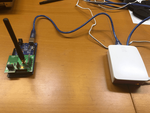
Afbeelding 1 : RFLink/Arduino via USB gekoppeld aan Raspberry Pi
Stel RFlink + Arduino in
De basis van het systeem is de RFlink-kaart aangesloten op een Arduino met de juiste software. De Arduino moet echter op USB worden aangesloten en kan helaas niet rechtstreeks op de Fibaro HC2 worden aangesloten. De Fibaro HC2 kan alleen via een API commando. Met tussenkomst van een Raspberri Pi is dit mogelijk vertalen.
Het RFlink-moederbord past mooi op het arduino-bord. De Arduino moet geprogrameerd worden met speciale software die hier te vinden is.
Ook de RFlink-lader voor Windows-toepassingen is er en met dit programma kun je codes al uitlezen en codes invoeren. Hiermee kun je de juiste opdrachten voor je apparaten opnemen. Wanneer je op een knop van een bestaande RF-afstandsbediening drukt, geeft het systeem dit op het scherm weer.
Houd er rekening mee dat het verzenden van codes meestal wordt gedaan door te beginnen met 10, hoewel de uitgelezen opdrachten worden voorafgegaan door 20 en met een volgnummer van de RF-berichten. Dit hoef je niet te doen bij het verzenden.
De instellingen voor het terminalprogramma zijn:
57600 baud, 8 databits, 1 stopbit, geen pariteit. Gebruik RAW-formaat in Putty met cr/lf.
IP naar serieel instellen via Raspberry Pi
Het lastige is om je Raspberry Pi te configureren om IP naar serieel (via USB) te vertalen. Hiervoor moet je de ser2net-software installeren die te vinden is via google of die al in je bibliotheek is maar nog niet is geïnstalleerd.
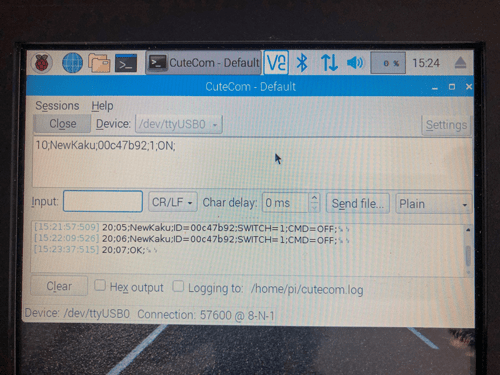
Om de juiste werking van de Rasberry Pi te testen, kun je ook Cutecom ook op de Raspberry Pi installeren om daarme de te verzenden commando's in te kunnen voeren.
RFLink-instructies voor seriële communicatie:
Alternatieve software:
Als alternatief kun je ieder terminalprogramma (zoals Realterm, Termite of minicom) gebruiken om verbinding te maken met RFlink en de RFLink-uitvoer te loggen.
Maak verbinding met de USB-poort met de volgende instellingen: 57600 baud, 8 databits, 1 stopbit, geen pariteit
Zorg dat CR / LF (regelterugloop / regelinvoer) wordt toegevoegd wanneer je opdrachten verzendt.
Stuur de volgende opdracht:
10; rfdebug = on;
Je zou een reactie moeten zien die er als volgt uitziet:
20; 03; RFDEBUG = AAN;
waarmee RFlink de debug-modus bevestigt
Dit bovenstaande commando zal naast de reguliere uitvoer ook de niet-gecodeerde RF-datapakketten tonen, zoals bijvoorbeeld:
20, 1D, DEBUG; Impulsen = 88; Pulsen (usec) = 225,2125,1225,975,1225,950,1225,950,400,975,1250,950,400,1000,1225,950,1225,975,1225,950,1225 , 950,1225,975,425,1000,400,950,425,1000,425,950,425,1000,1225,975,1225,950,425,1000,1225,975,400,975,425,975,425,1000,1225,950,425,1000,1250,975,1225,950,1225,975,425 , 1000,1225,975,1200,975,1225,975,400,1000,425,950,400,1000,1225,950,425,975,1225,950,1225,950,425,975,425,975,1225,950,1225;
20; 33; DEBUG; Impulsen = 40; Pulsen (usec) = 300.450.350.475.850.975.850.475.350.475.350.975.850.975.350.475.850.975.850.975.350.450.850.475.350.975.850.475.350.450.350.475.350.975.850.475.350.475.350;
Installeren van ser2Net op de Raspberry Pi
Volg onderstaande links om deze optie te installeren op je Raspberry Pi:
Dit is een voorbeel-configuratie file voor ser2net.
|
# format: |
|
# <TCP port>:<state>:<timeout>:<device>:<options> |
|
# TCP port |
|
# Name or number of the TCP/IP port to accept con- |
|
# nections from for this device. A port number may |
|
# be of the form [host,]port, such as 127.0.0.1,2000 |
|
# or localhost,2000. If this is specified, it will |
|
# only bind to the IP address specified. Otherwise |
|
# it will bind to all the ports on the machine. |
|
# |
|
# state Either raw or rawlp or telnet or off. off disables |
|
# the port from accepting connections. It can be |
|
# turned on later from the control port. raw enables |
|
# the port and transfers all data as-is between the |
|
# port and the long. rawlp enables the port and |
|
# transfers all input data to device, device is open |
|
# without any termios setting. It allow to use |
|
# /dev/lpX devices and printers connected to them. |
|
# telnet enables the port and runs the telnet proto- |
|
# col on the port to set up telnet parameters. This |
|
# is most useful for using telnet. |
|
# |
|
# timeout |
|
# The time (in seconds) before the port will be dis- |
|
# connected if there is no activity on it. A zero |
|
# value disables this function. |
|
# |
|
# device The name of the device to connect to. This |
|
# must be in the form of /dev/<device>. |
|
# |
|
# options |
|
# Sets operational parameters for the serial port. |
|
# Options 300, 1200, 2400, 4800, 9600, 19200, 38400, |
|
# 57600, 115200 set the various baud rates. EVEN, |
|
# ODD, NONE set the parity. 1STOPBIT, 2STOPBITS set |
|
# the number of stop bits. 7DATABITS, 8DATABITS set |
|
# the number of data bits. [-]XONXOFF turns on (- |
|
# off) XON/XOFF support. [-]RTSCTS turns on (- off) |
|
# hardware flow control, [-]LOCAL turns off (- on) |
|
# monitoring of the modem lines, and |
|
# [-]HANGUP_WHEN_DONE turns on (- off) lowering the |
|
# modem control lines when the connection is done. |
|
# NOBREAK disables automatic setting of the break |
|
# setting of the serial port. |
|
# The "remctl" option allow remote control (ala RFC |
|
# 2217) of serial-port configuration. |
|
# A banner name, signature, open string and/or close |
|
# stringmay also be specified. |
|
# The rs485 option takes RS485 related configuration. |
|
# The tw, tr, and tb options take a tracefile name ( |
|
# specified in TRACEFILE that will take all traced data. |
|
# tw is data written to the device, tr is data read from |
|
# the device, and tb is both. |
|
# |
|
# or... |
|
|
|
# BANNER:<banner name>:banner |
|
# This will create a banner, if the banner name is given in the |
|
# options of a line, that banner will be printed. This takes the |
|
# standard "C" \x characters (\r is carriage return, \n is newline, |
|
# etc.). It also accepts \d, which prints the device name, \p, |
|
# which prints the TCP port number, and \s which prints the serial |
|
# parameters (eg 9600 N81), and a large number of date related |
|
# items. See the man page for details.. Banners can span lines if |
|
# the last character on a line is '\'. Note that you *must* use |
|
# \r\n to start a new line. |
|
# |
|
# SIGNATURE:<signature name>:signature |
|
# This will create a RFC 2217 signature, that will be sent on clients |
|
# request. |
|
# |
|
# RS485CONF:<RS485 configuration name>:<RTS delay before send>:<RTS delay after send>:<RTS_ON_SEND>:<RX_DURING_TX> |
|
# This will create a RS485 configuration set, i.e. RTS delays before and after send as |
|
# also RTS logical level and receive configuration. |
|
# |
|
# TRACEFILE:<name>:filename |
|
# This specifies a filename to trace output into, as tw=/tmp/trace1. |
|
# This takes the same escape sequences as banners. |
|
# |
|
# OPENSTR:<name>:str |
|
# This specifies a string to be transmitted to the device when the |
|
# port is opened. This takes the same escape sequences as banners. |
|
# |
|
# CLOSESTR:<name>:str |
|
# This specifies a string to be transmitted to the device when the |
|
# port is close. This takes the same escape sequences as banners. |
|
# |
|
# CONTROLPORT:<port spec> |
|
# Allow the control port to be specified in the config file. |
|
# |
|
# Note that the same device can be listed multiple times under different |
|
# ports, this allows the same serial port to have both telnet and raw |
|
# protocols. |
|
|
|
BANNER:banner1:Welcome to ser2net TCP port \p device \d\r\n\ |
|
second line \ |
|
third line\r\n |
|
|
|
BANNER:banner2:this is ser2net TCP port \p device \d\r\n\ |
|
second line \ |
|
third line\r\n |
|
|
|
BANNER:banner3:this is ser2net TCP port \p device \d serial parms \s\r\n |
|
|
|
SIGNATURE:signature1:ser2net port ttyS2 |
|
|
|
RS485CONF:rs485port1:0:0:0:0 |
|
|
|
TRACEFILE:tw1:/tmp/tw-\p-\Y-\M-\D-\H:\i:\s.\U |
|
TRACEFILE:tr1:/tmp/tr-\p-\Y-\M-\D-\H:\i:\s.\U |
|
|
|
OPENSTR:open1:Open str\r\n |
|
|
|
CLOSESTR:close1:close str\r\n |
|
|
|
# Don't do this by default |
|
#CONTROLPORT:2000 |
Mijn instellingen
2000:telnet:0:/dev/ttyUSB0:57600 8DATABITS NONE 1STOPBIT banner
2001:telnet:0:/dev/ttyUSB0:57600 8DATABITS NONE 1STOPBIT banner
Om de juiste werking van de ser2net-configuratie te testen, kun je Putty op een pc gebruiken om de IP naar seriële setup te testen. Zorg ervoor dat je overschakelt naar de onbewerkte modus in Putty.
=~=~=~=~=~=~=~=~=~=~=~= PuTTY log 2019.04.28 12:29:12 =~=~=~=~=~=~=~=~=~=~=~=
ser2net port 2000 device /dev/ttyUSB0 [57600 N81] (Debian GNU/Linux)
20;3A;NewKaku;ID=00c47b92;SWITCH=1;CMD=ON;
20;3B;NewKaku;ID=00c47b92;SWITCH=1;CMD=OFF;
20;3C;NewKaku;ID=00c47b92;SWITCH=1;CMD=ON;
20;3D;NewKaku;ID=00c47b92;SWITCH=1;CMD=OFF;
10;NewKaku;00c47b92;1;ON:
20;3E;OK;
20;3F;NewKaku;ID=00c47b92;SWITCH=1;CMD=ON;
10;NewKaku;00c47b92;1;ON;
20;40;OK;
20;41;NewKaku;ID=00c47b92;SWITCH=1;CMD=ON;
20;42;NewKaku;ID=00c47b92;SWITCH=1;CMD=OFF;
10;NewKaku;00c47b92;1;ON;
20;43;OK;
20;44;NewKaku;ID=00c47b92;SWITCH=1;CMD=OFF;
^C10;NewKaku;00c47b92;1;ON;10;NewKaku;00c47b92;1;ON;
20;45;OK;
20;46;NewKaku;ID=00c47b92;SWITCH=1;CMD=ON;
20;47;NewKaku;ID=00c47b92;SWITCH=1;CMD=OFF;
10:NewKaku;
10;NewKaku;00c47b92;1;ON;
20;48;OK;
De laatste stap die moet worden gezet, is om de opdrachten voor RF te verzenden zoals vastgelegd met het RFlink-laderprogramma van Fibaro door een virtueel apparaat te maken.
Het virtuele apparaat bevat de volgende code
socket = Net.FTcpSocket("192.168.1.33",2000)
kaku = "10;NewKaku;00c47b92;1;ON;\r\n"
bytes, errorCode = socket:write(kaku)
Houd er rekening mee dat je de Raspberry Pi moet inschakelen als je een terminalprogramma zoals Putty hebt gebruikt voordat je Fibaro gebruikt. De seriale poort kan slechts door één apparaat tegelijkertijd worden gebruikt.
Het is duidelijk dat de codes op de juiste commando's moeten worden toegepast. Het IP-adres in het voorbeeld is 192.168.1.33 dat in mijn geval door de router is gegeven op basis van het Mac-adres van de Raspberry Pi (DHCP reservering). In mijn voorbeeld is het poortadres 2000.
In het RF-commando is de betekenis als volgt:
10; Standaard voor zenden
NewKaku; Naam van de Fabrikant
00c47b92: ID-Adres van het apparaat
ON; commando 'afgeluisterd' in een eerdere luisteractie
\r\n om carriage return en line feed aan de opdracht toe te voegen
Succes!!!
(met dank aan Walter)
